
Cone crushers are one of the most commonly used machines in the mining and aggregate industry. They play a crucial role in the crushing process, particularly in secondary and tertiary stages, where rocks and ores need to be reduced to finer sizes. Known for their high efficiency and ability to handle a variety of materials, cone crushers are essential in producing aggregates for construction and materials for industrial processes.
What is a Cone Crusher?
A cone crusher is a type of compression crusher that reduces material by squeezing it between an eccentrically rotating cone and a concave hopper. The material is fed into the top of the cone crusher, where it is crushed by the rotating cone and then discharged from the bottom. The working principle relies on the rock material being compressed between two surfaces, reducing its size until it reaches the desired output.
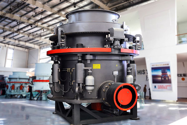
Components of a Cone Crusher
A typical cone crusher consists of several key components:
-
Frame – The frame provides the structure for the machine and supports the crushing process. It holds the components of the crusher, ensuring stability during operation.
-
Cone – The moving part that does the actual crushing. The cone is mounted on a rotating shaft, and as it moves, it creates pressure to break down the material.
-
Mantle – The mantle is the part of the cone that does most of the crushing. It is a moving piece that presses material against the stationary bowl (the concave).
-
Bowl (Concave) – The stationary counterpart to the mantle, it forms the surface against which the material is crushed. The shape of the concave plays a crucial role in determining the size and shape of the crushed material.
-
Drive mechanism – The cone is powered by a motor, which drives the mechanism that rotates the cone. This includes belts, pulleys, and sometimes gears.
-
Hydraulic system – Modern cone crushers often have a hydraulic system that allows for automatic adjustment of the cone’s position to regulate the size of the output material and protect the crusher from overloads.
-
Discharge port – This is where the crushed material exits the machine. The size of the discharge port can be adjusted to control the output size of the material.
Specifications – Technical Data
| Model | Cavity (coarse/fine) | Close Side feed opening(mm) | Min CSS (mm) | Capacity (t/h) | Power (kW) |
|---|---|---|---|---|---|
| HPT100 | C1 Extra Coarse | 140 | 19 | 75-140 | 90 |
| C2 Coarse | 100 | 13 | 60-110 | ||
| M Medium | 70 | 9 | 52-100 | ||
| F1 Fine | 50 | 9 | 50-95 | ||
| F2 Extra Fine | 20 | 6 | 45-90 | ||
| HPT200 | C2 Coarse | 185 | 19 | 145-250 | 160 |
| M Medium | 125 | 16 | 135-235 | ||
| F1 Fine | 95 | 13 | 115-220 | ||
| F2 Extra Fine | 75 | 10 | 90-190 | ||
| F2 Extra Fine | 80 | 10 | 110-240 | ||
| HPT300 | C1 Extra Coarse | 230 | 25 | 220-440 | 250 |
| C2 Coarse | 210 | 19 | 190-380 | ||
| M Medium | 150 | 16 | 175-320 | ||
| F1 Fine | 105 | 13 | 145-280 | ||
| F2 Extra Fine | 80 | 10 | 110-240 | ||
| HPT400 | C1 Extra Coarse | 295 | 30 | 300-630 | 315 |
| C2 Coarse | 251 | 25 | 285-560 | ||
| M Medium | 196 | 20 | 250-490 | ||
| F1 Fine | 110 | 13 | 180-345 | ||
| F2 Extra Fine | 90 | 10 | 135-320 | ||
| HPT500 | C1 Extra Coarse | 330 | 38 | 425-790 | 400 |
| C2 Coarse | 290 | 30 | 370-700 | ||
| M Medium | 210 | 22 | 330-605 | ||
| F1 Fine | 135 | 16 | 270-535 | ||
| F2 Extra Fine e | 95 | 13 | 220-430 | ||
| HPT800 | C1 Extra Coarse | 350 | 38 | 570-1200 | 630 |
| C2 Coarse | 299 | 32 | 520-1050 | ||
| M Medium | 265 | 25 | 475-950 | ||
| F1 Fine | 220 | 16 | 370-800 | ||
| F2 Extra Fine | 150 | 13 | 310-600 |